Design
The design of this library is based on the transformation of the Assimp scene graph to a Scene Kit scene graph.
Classes
The class diagram for the code in Code/Model is shown below.
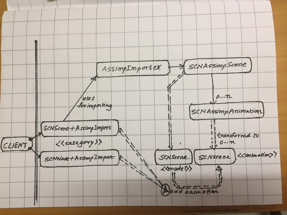
AssimpImporter is the most important class which transforms the assimp scene graph to the scene kit scene graph. It does the transformation by doing a depth first traversal of the assimp scene graph and for each assimp node visited, it generates a scene kit node.
SCNAssimpScene contains all the transformed data, excluding the animation data, for which SCNAssimpAnimation is the container. The SCNAssimpScene generates the model SCNScene and animation SCNScene instances. The SCNNode+AssimpImport category contains method to add the animation.
Generating the scene kit scene graph
The scene kit scene graph is generated in a 3 pass process:
- Pass 1: Generate the scene graph with geometry, materials and camera. In this pass, we also collect the bone names if the aiMesh has bones.
- Pass 2: This pass is executed only if the file has skeletal animation data, in which case, we infer all the skeleton info so that we can make a SCNSkinner and then generate the animation data using CAAnimation objects.
- Pass 3: Finally we transform the generated scene graph to a SCNScene and
each animation generated in pass 2 to SCNScene. This transformation is
important as it makes it easy to both serialize to native
.scnformat and integrate into asset pipelines and/or applications.
Each pass is further described in detail next.
Pass 1: Generating the graph with geometry
Generating Geometry
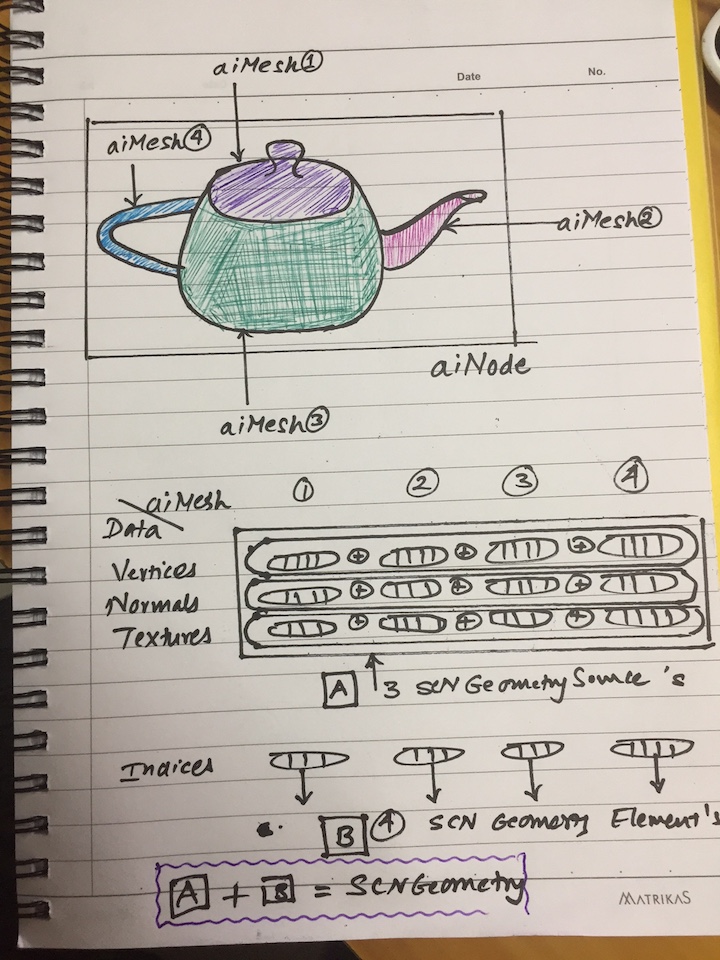
The assimp node can contain mulitiple meshes where each mesh maps to the SCNGeometryElement. The importer generates a single SCNGeometrySource for each of vertex, normal and texture data for all the meshes in the nodes. Next it generates separate SCNGeometryElement for each mesh in the data, ensuring the vertex indices are offset correctly for the combined geometry source.
A visual representation of this transformation is as shown.
Generating Materials
As seen in the visual for geometry transformation, the importer now generates a material for each mesh in the node. The material in assimp maps to SCNMaterial in scene kit. The importer generates a image object for a texture or a color object for a color if available for the following material properties: diffuse, specular, ambient, reflective, opacity, normals, height, displacement and light map. Both embedded and external textures are supported. The material property in assimp maps to SCNMaterialProperty.
Pass 2: Generating Skeletal Animations
The skeletal animation data is generated in a 3 step process which consists of:
- Making a skeleton database
- Making a scene kit skinner
- Making the core animation objects
Making a skeleton database
The assimp scene graph does not contain a unique list of bones or the root of the skeleton which have to be inferred from the assimp data structures.
We parse the data structures above, so that we have a list of unique bone names, bone nodes and the bone inverse transforms. Once the unique bone nodes is known, the importer determines the root of the skeleton as that node which has the lowest depth from the parent!
Making a skinner
In order to make a skinner, we also need the vertex weights data in addition to the bone nodes and their inverse bind transforms which are available from Making a skeleton database.
Assuming each vertex is influenced by 2 weights, the scene kit skinner data layout is as such.
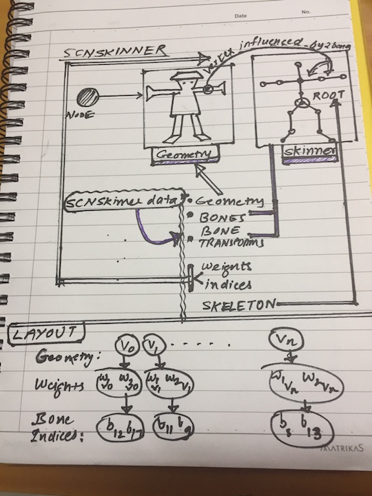
The importer first finds the number of vertices at the node and the maximum weights. As a node may contain multiple meshes, the weights information is generated for the combined meshes at that node and if a given node has less weights than the maximum weights, zero weights are added for the remaining weights.
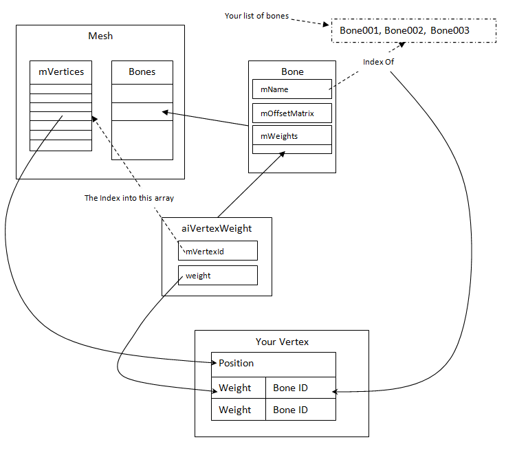
In assimp, each mesh’s bones have vertex weights from which we have to calculate the inverse data of which vertices are influenced by which bones.
When calculating the bone indices for the corresponding bone weights, we pass the unique array of bone names which we will use when constructing the skinner so that the bone indices are as per skinner’s bone indices layout. Again here, we translate from the assimp bone name to the index in the array of bone names generated when making the skeleton database.
If you combine the visuals of the assimp data structures and map them to the SCNSkinner, and understand the skeletal animation concept of vertex deformation using bone weights, then the above will be easier to understand.
Making the animations
The animation data is stored in aiAnimation as shown.
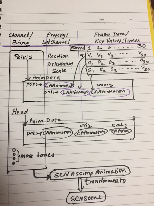
Each channel represents a bone and contains the keys for position, orientation
and scale. The position, orientation and scale keys are then converted into a
CAAnimation object. Each position and scale key value is represented by a
SCNVector3 while the orientation is represented by a SCNVector4 which is a
quaternion. These core animation objects are stored in a dictionary keyed by
position, orientation, scale, along with a generated animation name, gives
us a SCNAssimpAnimation object.
If we have multiple animations in a file, we end up with multiple SCNAssimpAnimation instances.
At the end of pass 2, we end up with SCNAssimpScene instance with SCNAssimpAnimation objects if animation data exists.
Pass 3: Generating native SCNScene instances
The SCNAssimpScene instance is now transformed into a SCNScene instance. Each SCNAssimpAnimation instance is transformed into a SCNScene instance. By transforming these to SCNScene instances, both serialization and integration into existing asset pipelines and/or applications becomes trivial.
Loading Animations
The SCNNode+AssimpImport category defines a method to add the animation. As all the animation data is just CAAnimation objects, the animation SCNScene graph is traversed and the core animation objects are added to the corresponding bone node in the target scene or target nodes’ subtree.
Testing
The common test code place in Code/Library/Tests tests all the models in the assets directory filtered by all the File formats supported.
Each model is tested in AssimpImporterTests for:
- Structure where each node in the scene kit graph has the same data as the corresponding node in the assimp scene graph.
- The model and animation SCNScene’s generated by SCNAssimpScene are
serializable to the native
.scnformat without any errors. The serialized files are generated in a temporary test directory, which is deleted after the test run.
There also exists a test SCNSceneTests for testing the file formats supported.